|
This section is to be read in conjunction with the test certificate and is just a summary to help when requiring readings to be taken.
12.1 The first tests refer to section 2a and 2c where pressure readings are required. A manometer is connected to the pressure test point with the quick release fitting. Follow the requirements on the test certificate.
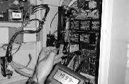
12.2 Section 3a requires the full load voltage of the control circuit. With the power on, measure the DC control voltage between B- and AF.
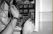
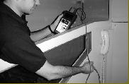
12.3 Section 3b is to check the insulation resistance to earth. Switch the power off and remove the connection to the battery. Isolate the PCB by removing all the connectors that plug into it also ensuring that B- is separated from the earth. Using a megger, measure the insulation resistance between the earth stud in the control panel and each of the trailer connections.
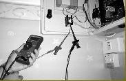
12.4 Section 3d is to check the maximum continuity to earth. With the power switched off, measure the continuity between the earth stud in the control panel and at various exposed metal parts within the cabinet and on the gantry.
12.5 Section 3j asks for the actual running current with full load. With the power switched off, remove the red wire connected to the bottom terminal of the thermal overload. Connect the multimeter in between (series) with the wire and the terminal making sure that the meter is set to read AC current. Switch the lift on and record the current reading when the lift is travelling in the up direction fully loaded. After taking the reading, switch off the power to the lift, remove the meter and replace the wire onto the overload terminal. CAUTION, ENSURE THAT THE LIFT IS ISOLATED WHEN IN CONTACT WITH THE RED WIRE OR TERMINAL.
|
|


